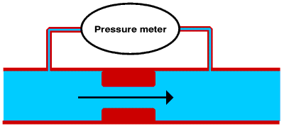
In many ways we can think of the flow of electricity through wires and lamps and switches etc. as being similar to the flow of water through the pipes and plumbing system of a house.
If we have a water pipe with some sort of a restriction in it, water will not flow through the pipe unless there is a pressure difference across the restriction.

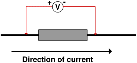
The rate at which the water flows through the pipe depends upon the size and shape of the restriction and the pressure difference across it. For example water will pass through the pipe carrying the water from the cistern to the lavatory bowl when we flush it at more than two litres a second even though the water pressure is quite low, whereas a dripping tap might pass less than a litre of water an hour even though the water is at mains pressure.

Similarly the rate at which electricity flows through a resistor depends upon its resistance and the p.d. across it. We measure resistance in ohms, after Georg Ohm (1787 - 1854). The symbol for ohms is Ω, a capital omega, the last letter of the Greek alphabet.
As an aside, the first letter of the Greek alphabet is alpha, which is why we use alpha and omega for the first and the last. The second letter of the Greek alphabet is beta, hence our word alphabet (from alphabeta).
The unit of electrical charge is the coulomb, symbol C, after Charles Augustin de Coulomb (1736 - 1806). So we measure the flow of electricity (electric current) in coulombs per second. We call a current of one coulomb per second one ampere, symbol A, after André Ampère (1775 - 1836), although today most people miss out the accent. We often talk about amps rather than amperes although we should always write it as amperes or A.

Many people have some difficulty with volts and amps. The key to mastering the difference between them is to mentally substitute potential difference for volts and coulombs per second for amps and think of water flowing through a restriction. This helps you to understand that volts is a pressure difference and amps a rate of flow.
The resistance of anything that conducts electricity is defined as the ratio of the voltage across it to the current through it, so algebraically
If a current of 3 A flows through a resistor with a resistance of 6 Ω the voltage across the resistor is 3 A × 6 Ω or 18 V
If there is a potential difference of 24 V across a resistor and the current through the resistor is 2 A then the resistance of the resistor is 24 V ÷ 2 A or 12 Ω
If there is a p.d. of 15 V across a 5 Ω resistor then the current through the resistor is 15 V ÷ 5 Ω or 3 A
There are some more worked examples on another Page.
Here we have a pipe with two restrictions, A and B in it

What goes in at one end of the pipe must come out of the other, that is, the flow through B must be the same as the flow through A. But although the flow rate is the same, the pressure difference needed to force the water through B at this rate is bigger that needed to force it through A.

Here we have a 3 Ω and a 5 Ω resistor in series, that is, the electricity flows first through one and then the other. The current through both is 8 A. The p.d across the 3 Ω resistor is therefore 3 Ω × 8 A or 24 V; similarly the p.d. across the 5 Ω resistor is 40 V.
The total p.d. across both resistors is therefore 24 V + 40 V or 64 V, and so the total resistance is 64 V ÷ 8 A or 8 Ω, that is, 5 Ω + 3 Ω.We have a 4 Ω resistor in series with a 12 V battery. Calculate the current.
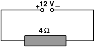
The current is 12 V ÷ 4 Ω or 3 A.
Now we add a 8 Ω resistor in series. Calculate the new current.

The total resistance of the circuit now becomes 4 Ω + 8 Ω or 12 Ω so the new current is 12 V ÷ 12 Ω or 1 A.
These calculations, and many other calculations of this sort, assume that the resistance of a resistor does not change when the current through it changes. If this is true the graph of I against V is a straight line, and the resistance is the slope of this line. For most metals the resistance does not change with the current until the current is so high that the metal gets very hot. Ohm did a lot of work on electrical circuits but always with metal wires and components at room temperature. Ohm’s Law states that the current is proportional to the voltage, so doubling the voltage doubles the current, but Ohm’s Law is only true if the resistance stays the same. So any device for which Ohm’s is true is called a liniar or ohmic device. Most wires made from metals and resistors made from them are liniar or nearly so, and so were most of the materials and components available to Ohm, but modern low energy lamps and most electronic components are not. Ohmic and non-ohmic devices are discussed at the end of this Page; in all the calculations following all the wires and other components are taken to be liniar. But remember the resistance is defined as the ratio of the voltage to the current, so is always the slope of the line at that point even if the line is not straight.
A buzzer is powered by a 12 V battery, and carries a current of 4 A. This makes it too loud. What value resistor must we put in series with the buzzer to reduce the current to 3 A?
When the current is 4 A the resistance must be 12 V ÷ 4 A or 3 Ω. To reduce the current to 3 A the new total resistance must be 12 V ÷ 3 A or 4 Ω so we must add a 1 Ω resistor.
There are some more worked examples on another Page.
There are two special cases. The first is where one resistor is very much lower than all the others.
Here we have a 100 Ω resistor in series with a 0.01 Ω resistor connected to a 5 V power supply.
The total resistance is 100.01 Ω so the current is 5 V ÷ 100.01 Ω or 0.049995 A. The voltage drop across the 100 Ω resistor is 100 Ω × 0.049995 A or 4.9995 V, and that across the 0.01 Ω resistor is 0.01 Ω × 0.049995 A or 0.00049995 V. (These do not quite add up to 5 V because of rounding errors inside my calculator.)
In all the earlier examples we have ignored the resistance of the wires. This example shows that provided the wires have a very low resistance, for all but the most accurate work we are usually justified in doing so. (Excluding the people who supply us with our electricity and look after the cables which bring it to us of course!) The voltage drop along a wire is given by V = I × R so if R is very low then V is very low unless I is very high. This is what may happen if there is a short circuit: short circuits are discussed on the Page on Parallel Circuits.
In the second special case one resistor is very much bigger than all the others.

The total resistance is 100 100 Ω, so the total current is 5 V ÷ 100 100 Ω or 0.00004995 A. The voltage drop across the 100 Ω resistor is 0.00004995 A × 100 Ω or 0.004995 V, while that across the 100 000 Ω resistor is 0.00004995 A × 100 000 Ω or 4.995 V. As before these do not quite add up to 5 V because of rounding errors in my calculator.
What this means is that if one resistor is very very high the current in the whole circuit is very very low. The p.d across the very high resistor is very nearly the p.d. across the whole circuit, and the p.d across the rest of the circuit is almost zero.
These two special cases come together in a simple switch. We can think of a switch as something which has no resistance when it is closed and passes no current when it is open.
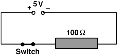
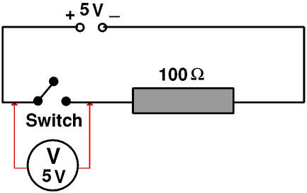
When the switch is closed it has no resistance. So the total resistance is 100 Ω, the current is 5 V ÷ 100 Ω or 0.05 A, the voltage drop across the 100 Ω resistor is 0.05 A × 100 Ω or 5 V and the voltage drop across the switch is 0.05 A × 0 Ω or 0 V (Surprise!)
When the switch is open there is no current in the wires and so no voltage drop along them. This means that the potential difference across the switch is the potential difference applied to the circuit as a whole.
If you are one of the many people who have difficulty in understanding how we can have a voltage without a current think of, or better still actually take, a party balloon. Blow it up and tie a knot in it to stop the air escaping. Stick a piece of Sellotape® or similar onto it, and stick a pin through the Sellotape. Now stick a pin into the balloon anywhere else.
Usually if you stick a pin into a blown up balloon the rubber will rip and the balloon will explode with a loud bang. If however you stick the pin into the balloon through the Sellotape the Sellotape will stop the balloon fabric from ripping, and you will just make a small hole. Because there is a pressure difference between the air inside the balloon and the air outside it air will come out of the hole - the smaller the hole the slower the flow. If you do not make a hole in the balloon no air will come out - but there is still a pressure difference between the inside and the outside.
Alternatively, look at this circuit for a lamp in your house.

When the switch is off there is no current in the live wire so no voltage drop along it. Every part of it is at 230 V. Similarly every part of the neutral wire and the wire from the switch to the lamp is at 0 V, so there is a p.d of 230 V across the switch and if you touch the wires inside it you may get a shock. But the lamp and the black and blue wires are all at 0 V so you can change the lamp quite safely.

Metals and wires made from them are usually liniar or almost so, and so when Ohm was doing the experiments which led to him putting forward his Law he found the graph of voltage against current was a straight line. The slope of the graph was constant; he called this the resistance.
The resistance of metals depends upon the temperature, so metals are approximately liniar until the current is high enough to make the wire hot enough to change the resistance. This of course is the case for an “incandescent” (old style )light bulb: these work because the current is high enough to make the filament glow white-hot. When it is is at its operating temperature the filament has a much higher resistance than when it is cold. So when you first switch on such a bulb the resistance is much lower and so the current is much higher than when it is running - this is why such bulbs are most likely to fail at the instant you turn them on, and the more powerful the bulb the more likely this is to happen. You can make such bulbs last longer by using a dimmer switch to turn them or a special electronic circuit including a thyristor. You may notice that when you are watching an old film, if a man walks into a dark room and turns on the light, the light in the room (that is, the studio lighting on the film set) comes on quite slowly.
Most low-energy lamps and electronic components are non-liniar, that is, the graph of voltage against current is not a straight line, but the resistance of the component at any voltage and current is still the slope of the voltage/current line at that point.