Archimedes is supposed to have said “Give me a long enough lever and a place to stand and I can move the Earth.” There are several ways we can lift a bigger weight than we can by using just our own muscles. One is to use a lever, and this Page is about levers; other Pages discuss pulleys and ramps.

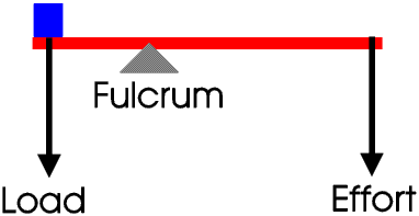
The force we apply is called the effort, the force exerted by the load is called, surprise, the load, and the pivot point is called the fulcrum. The long thin thing (although it need not be long, or thin, or even straight) the load and effort are acting on is usually called the beam. In Diagram A the effort is twice as far from the fulcrum as the load, so (if there is no friction at the fulcrum) the effort is half the load.
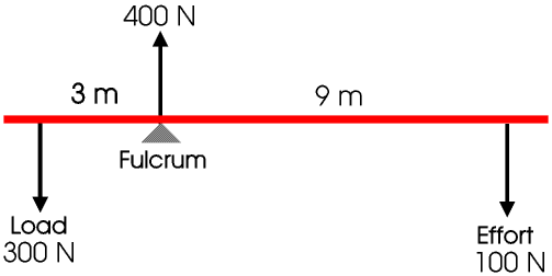
Here a load of 300 N acts 3 m from the fulcrum and is balanced by an effort of 100 N 9 m from the fulcrum.
The load and effort are trying to turn the lever in opposite directions. The moment of a turning force is the product of the force and its perpendicular distance from the fulcrum, and is measured in newton metres. Here the clockwise moment is 9 m × 100 N or 900 newton metres, and the anticlockwise moment is 3 m × 300 N or 900 newton metres. For any lever that is balanced (not moving) the total clockwise and anticlockwise moments must be the same.
Archimedes forgot one thing: to move the Earth you need not only a very long lever and somewhere to stand but also a fulcrum. For a lever like this the force on the fulcrum is the sum of the load and the effort so will exceed the weight of the Earth...
(Actually Archimedes, who was one of the greatest scientists of all time, understood the lever very well. He lived from 287 - 212 BCE, and this story is just one of many much later stories about him, most of which are simply not true, at least in the form they are told today.)
In both these arrangements the load and effort are on opposite sides of the fulcrum. This is called a Class 1 lever. Usually in a Class 1 lever we want the load to be bigger than the effort. The mechanical advantage is the ratio of the load to the effort (that is load over effort): if there is no friction, in Diagram B the mechanical advantage is 3. Friction at the fulcrum will mean we need to use a bigger effort for the same load so the mechanical advantage will be less.
If you cannot remember whether the mechanical advantage is load over effort or effort over load just remember that usually we want to get a big force for a little effort, so the bigger the advantage the better. To get a big number we divide a big number by a small number not a small number by a big number.

The force at the fulcrum is 1400 N. We do not always show the force at the fulcrum on diagrams but we must never forget that it is there.
Nature never gives us something for nothing.

Here, ignoring friction, the load is four times the effort but the distance moved by the effort is four times the distance moved by the load. The ratio of the distance moved by the effort to the distance moved by the load is called the velocity ratio. If there is no friction at the fulcrum the velocity ratio and mechanical advantage are equal.
The work done when a force moves its point of application is the product of the force and the distance moved. Work is measured in joules. If a force of 200 N moves 3 m the work done is 600 J.
Although both work and moment are obtained by multiplying a force by a distance they are not at all the same. In one the distance is measured in a direction at right angles to the direction of the force and in the other in the direction of the force. Work is measured in joules and moment in newton metres.
The efficiency of a lever, or any other machine, is the ratio of the work done on the load to the work done by the effort. It is usually given as a percentage. We can easily show that

If there is no friction at the fulcrum the efficiency of a lever is 100%.
When we think of a lever we usually think of a Class 1 lever where the load is bigger than the effort, that is, with a mechanical advantage of more than one, but it does not have to be this way. A child’s see-saw is a Class 1 lever but it would not be a lot of fun to play on if the mechanical advantage and velocity ratio were not one, or very nearly.

But a Roman ballista, used for firing large stones at the wall of a town being attacked, was a Class 1 lever with a velocity ratio of a lot less than one, so that the stone and basket moved much faster than the effort.
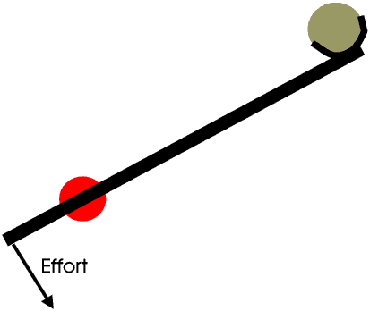
A steelyard is a Class 1 lever, where a weight can be slid along a calibrated beam until it balances. In the Middle Ages they were a very common type of weighing machine (balance) but they are less common today.
They are called steelyards because in the Middle Ages they were often made of steel and were about a yard long.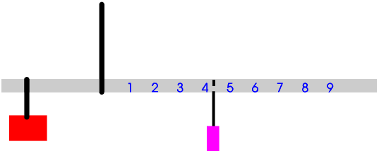
Often we use a lever (almost always Class 1) as a counter-balance, hence of course the word counterweight.
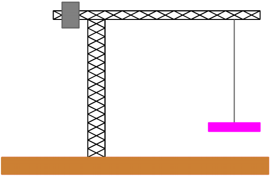
Without the counter-weight the crane would certainly fall over. The mediaeval cathedral builders, with their very tall very thin columns, were faced with a similar problem, but they solved it in a different way - this is described on another Page.
In a Class 2 lever the load acts between the effort and the fulcrum.
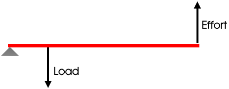
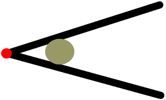
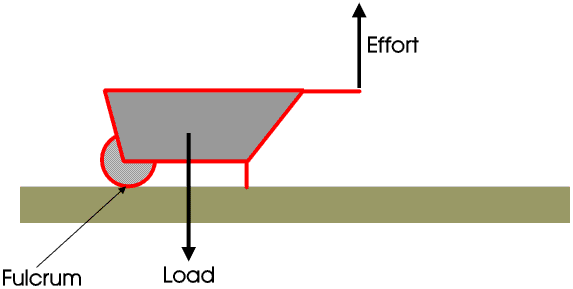
In a Class 2 lever the mechanical advantage and velocity ratio are always greater than one. A nutcracker and a wheelbarrow are examples of Class 2 levers.
Here is another Type 2 lever, used for drawing water out of a well. The rope is wound onto a rotating drum.
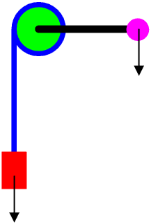
The handle can be turned by hand, or you can turn the shaft by using a donkey in a wheel like a hamster wheel. The anchor on a sailing ship is raised using a capstan. Here the shaft is vertical and the sailors walk round pushing on bars which fit into it. The bars can be removed and stored in a special rack so that they are not on the way when the capstan is not actually being used. The anchor cable goes down through a small hole in the deck.
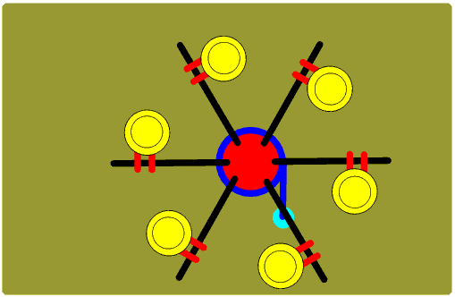
This is a Mexican ship which is why the sailors are wearing big hats.
In a Class 3 lever the effort acts between the fulcrum and the load. The mechanical advantage and velocity ratio of a class 3 lever are always less than one.
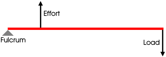
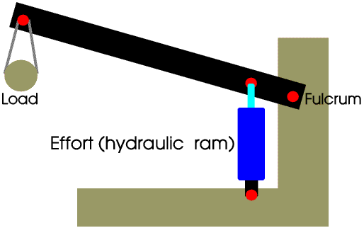
Class 3 levers are used mainly to produce a large movement of the load for a small movement of the effort. For example hydraulic rams have only a small movement and can only exert a push not a pull, so class 3 levers are used on JCBs and heavy lifting gear etc.
In our bodies, our muscles work by getting slightly shorter and fatter but can only exert a pull not a push. So each joint needs two muscles, one to move it one way and the other the other.
Almost all our joints are both class 1 and class 3 levers, each with a mechanical advantage of less that one. The biceps produces the effort in a class 3 lever and the triceps the effort in a class 1 lever.
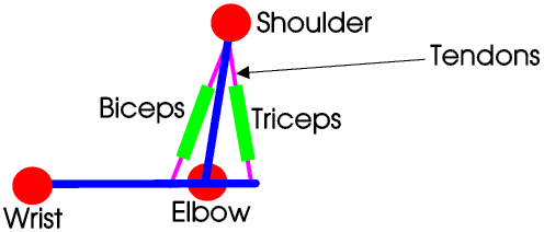
This drawing greatly exagerates the distance between the fulcrum (elbow joint) and the effort (point at which the tendon is attached to the bone). In most of our joints this distance is only a few millimetres, which is why many people do not notice it and so fail to realise that our bodies are worked by levers.
Quite often the tendons are very much longer than the muscles, and the muscles themselves are not where we expect them to be, for example the muscles which work our fingers are actually in our forearm, between our wrist and elbow. You can prove this for yourself by watching and feeling what happens when you squeeze someone's hand.