 will bring you back to this point. (The Eye of Horus
 It is designed primarily for teenagers working towards school leaving exams and is non-mathematical, but it also contains a lot of background and historical information and is not restricted to topics which are included in school-leaving exams, so it may also be helpful or interesting to older people who did not study electronics at school.
When you walk into a room and turn on the light you are using your fingers to move a piece of plastic which moves another piece of plastic which moves a piece of brass so that it touches another piece of brass. This allows a current to flow in an electrical circuit and the light comes on.
You are using a mechanical switch. A mechanical switch has moving parts. It is also possible to control an electrical circuit using an electronic switch, where the switch is operated entirely by electricity and there are no moving parts (except the electrons of course).
The electronic components (diodes, transistors, LEDs LCDs, LDRs, etc - these are explained later) in a circuit contain no moving parts. Electronics is about things (everything from whole Air Traffic Control Systems to toothbrushes) which include electronic components. They will also almost always contain at least one mechanical component, even if it is only the ON/OFF switch. (Yes it is true: a teenager’s mobile phone really does have an OFF switch - I have seen it.) The microchip on your debit card or passport or in your dog does not contain any moving parts, not even an ON/OFF switch; the total system controlled by the computer in the film War Games contained lots of moving parts, including inter-continental ballistic missiles, but did not have an OFF switch.
Originally things which were partly electrical and partly mechanical were called electro-mechanical, but today in many devices the electronics are so important that the word mechatronic is often used. Industrial robots and Martian Landers are mechatronic.
A relay uses the current in one circuit to operate a switch controlling the current in another circuit. Relays may be mechanical or electronic. We usually use a mechanical relay to switch circuits involving high voltages or currents. A mechanical relay used to switch a high voltage or current is often called a solenoid. A mechanical relay usually includes an electromagnet: switching on the first circuit activates the electromagnet which attracts a piece of iron which operates the switch in the second circuit.
The commonest electronic relay is a transistor: on a silicon chip there are twenty five million transistors per square millimetre, most of which are being used as switches.
A good example of a mechanical relay is the starter solenoid in a motor car. We need a powerful electric motor to start the engine, and this needs a very large current, up to or even exceeding 200 A. It would be quite impossible to put a switch big enough to carry this current near the driving seat, so instead we use a relay. The switch the driver operates to start the engine (usually by turning the car key) carries only a very small current.
We often divide substances into metals and non-metals, and say that metals conduct electricity and non-metals do not, but there is also a group of substances which sometimes conduct electricity in one way and sometimes in a totally different way: the way they work can be changed by electricity, or in other ways for example by light. We call these substances semi-conductors, and today semi-conductors are a vital part of almost every electronic circuit. There are a few naturally occurring semi-conductors but today most semi-conductors are Man-made.
Naturally occuring semi-conductors were used in some very early (“cats’ whiskers”) radio receivers - this is described later on this Page
Man-made semi-conductors are usually made from silicon or germanium which are metalloids (or semi-metals), the elements that come between the metals and non-metals in the Periodic Table, and there is more about them on my Chemical Elements Page.
To understand the next Paragraphs in this Section it might be helpful if you have a copy of the Periodic Table in front of you.
In a silicon crystal each atom is fixed in a position in a lattice. Each silicon atom has four electrons in its valence (outermost) shell, and each of these is shared by one of the four silicon atoms surounding it. So these electrons are not free to move, and silicon is a non-conductor. (Germanium also has four electrons in its outermost shell and so can also be used to make a diode. To understand the valence shells of elements in Periods 4 and 5 which include the transition elements we need to know a little about p and s orbitals but I hope you can still understand what follows without it.)However, arsenic has five electrons in its valence shell, so if we add a small amount of arsenic to the silicon crystal each added arsenic atom will take the place of a silicon atom in the lattice and so there will be an electron at this point which is not fixed into the lattice but is free to move. Neither the silicon nor the arsenic are charged, nor can they move, but electrons have a negative charge so the arsenic atom has become a negative charge carrier. Adding arsenic in this way is called doping, and the doped silicon is called n-type silicon, because there is now an abundance of negative charge carriers in the lattice.
Similarly gallium has three electrons in its valence shell, so if we dope the silicon with gallium there will be a space where an electron would be at each point in the lattice where a gallium atom has replaced a silicon atom. We can think of this space as a positively charged hole, so the gallium atoms are positive charge carriers. An electron can move into this hole but when it does so it leaves a hole somewhere else. A hole disappears at one point and at exactly the same time a hole appears somewhere else! So this hole behaves as though it is a positively charged particle which moves around just like an electron. This is called p-type silicon because there is an excess of positive charge carriers.
If we take a silicon crystal and dope it in such a way that an area of n-type silicon touches an area of p-type silicon we have an np junction.These np junctions form the basis of almost all circuits involving semiconductors.
If we take an np junction and fix wires to each of the areas we have a diode, so called because it has two wires.
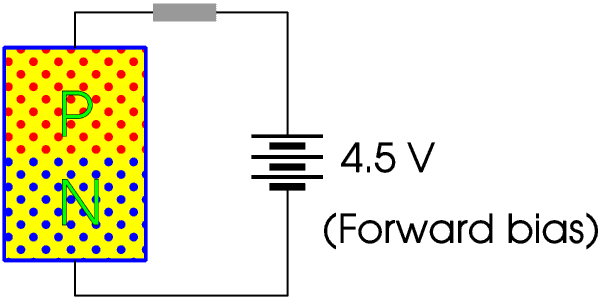
Here we have a diode connected to a battery, with the p-type silicon connected to the positive terminal and the n-type silicon connected to the negative terminal. This is called forward bias.
Once a forward bias has been applied electrons are free to move from an area with a surplus of negative charge carriers (electrons) to an area with a surplus of positive charge carriers (electron holes) so they can move from the n-type silicon to the p-type silicon, that is, a current passes across the boundary and in the circuit.
Here we have the same arrangement, only reverse biased, with the positive terminal of the battery connected to the n-type silicon, and the negative terminal attached to the p-type silicon.
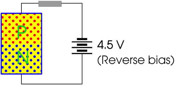
The electrons cannot pass from the p-type silicon (surplus of holes) to the n-type silicon (surplus of electrons), so there is no current across the boundary.
Splitting hairs, it is not impossible for electrons to pass from the p-type silicon to the n-type silicon, just very very very difficult. So when the junction is reverse biased the current through it is not zero, just very very very small. In the real world we often encounter situations like this, where an event is not impossible, just very very very unlikely, for example coming home from school and finding your house has been painted bright blue by a team of Italian sumo-wrestlers. Sometimes, as in this case, it is safe to ignore the possibility; sometimes, for example when we are designing an aeroplane, it is not. In everything that follows I am ignoring it: the current through an np junction when it is reverse biased is taken to be zero.
The diode allows a current to pass through it when it is forward biased but not when it is reverse biased. Diodes have very many uses in electronics, but one of them is to convert an a.c. current to d.c. A diode used to convert an a.c. current of more than a few milliamperes to d.c is usually called a rectifier. Rectifiers are described on another Section.
Some of the charge carriers (that is, the atoms used to dope the silicon) very close to the boundary between the two dosed areas may diffuse across it, so there are negative charge carriers in the p-type silicon and positive charge carriers in the n-type silicon. This creates a very narrow zone which is difficult for electrons to cross. So a diode does not begin to work properly until the forward bias voltage is greater than about 0.7 V (or about 0.3 V for germanium).
But when we draw a circuit diagram what is the symbol for a diode? Read the next Section!
If you take off a nylon shirt in a quiet dark room you can both hear and see the sparks flying. I am told you get the same effect with a nylon blouse but I have never tried this for myself. This effect is due to “static electricity”.
Two thousand five hundred years ago the Ancient Greeks did not have nylon, so they had to make their clothes out of natural materials such as wool, cotton, linen, silk, leather and fur. Jewellery was made mainly from gold and silver, with precious and semi-precious stones such as rubies, emeralds, sapphires, opals, amethysts, beryls and jade. This sort of jewellery does not usually produce static electricity. But Greek ladies were also very fond of amber jewellery, and if a lady walked down the road wearing a dress with a fur collar and an amber necklace the sparks really flew!
The Greek for amber is elektron, hence our word electricity.
It is “obvious” that if you rub amber with fur something happens to the amber, it is much less obvious that something also happens to the fur. Similarly if you rub glass with silk it is “obvious” that something happens to the glass but much less obvious that something also happens to the silk. So for the next two thousand years electricity (what today we would call static electricity) was about glass and amber not silk and fur. Even today you can rub a balloon against your jumper and stick it to the wall or pick up bits of paper with it and everyone thinks you are clever, but no one thinks about your jumper.
By about 1730 it was thought that there were two different sorts of electricity, one on materials such as glass and the other on materials such as amber, and that these different types repelled each other. In 1733 the French scientist Charles du Fay (1698 - 1739) named these two types of static electricity “vitreous” (from the Latin for glass) and “resinous” (amber being from a resin), but later they were renamed “positive” and “negative”. They could have decided to say that resinous was positive and vitreous was negative but no, they had to decide that vitreous was positive and resinous was negative, and today this causes endless confusion to young people learning about electrolysis and semi-conductors.
Today when we talk about electricity we usually mean the sort of electricity which flows along wires, from positive to negative. But until the invention of the battery (in 1800) and the dynamo (in 1831) the only sort of electricity people knew about was static electricity. It was the English scientist Michael Faraday (1791 - 1867) who was able to show that vitreous and resinous electricity, lightning, the electricity produced by a battery, and the electricity produced by a dynamo, are all the same.
The only problem is that once we decided to say that glass rubbed with silk has a positive charge then the electron, discovered in 1887, has a negative charge, so a current passes from positive to negative only because the electrons which are actually carrying it are passing from negative to positive!
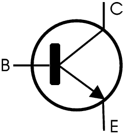
Transistor is actually the name given to a number of different electronic devices which switch or amplify electric currents, but here is the simplest, consisting of two np junctions back to back - a bipolar junction transistor or BJT. (If you do not understand what a junction is or how it works please go back to the Section on diodes.)
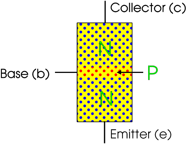
This is a npn triode because it has three connections (do I need to tell you why it is called npn? - there are also pnp transistors) and is a very common transistor, and when people talk about “a transistor” this is usually what they mean, and for the rest of this Page it is what I mean.
The p-type layer is actually very thin indeed, on a drawing this size you would not even see it.

Electrons can pass from the n-type to the p-type but cannot pass from the p-type to the n-type so no current flows.
If however we forward bias the lower junction electrons will flow in this circuit from the n-type to the p-type. There is an imaginary “wall” trying to stop the electrons passing from the p-type to the n-type and so on to the collector but this wall is so low (that is, the base is so thin) that most of the electrons just jump over it! So the electrons flow all the way from the emitter to the collector, and of course a current flows from the collector to the emitter. Hence the names, the emitter emits electrons and the collector collects them.
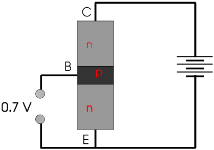
So applying a low voltage to the base acts as a switch for the collector-emitter current. Not only that, the collector-emitter current is many times higher than the base-emitter current. So we can use a transistor as both a switch and a current amplifier.
Here is the symbol for a npn transistor.
A transistor has three normal operation modes, cut-off, active, and saturation.
In effect, the resistance of the collector-emitter circuit starts very high in the cut-off mode, then falls slowly in the active mode, until it becomes almost zero in the saturation mode.
Transistors are used in a huge range of applications: a large transistor can handle powers of more than 100 W, although each of the twenty five million transistors on every square millimetre of an integrated circuit on a silicon chip can handle rather less than that!
Here is a very simple circuit containing just a battery and three resistors.
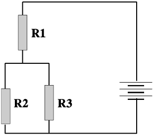
The current through R1 is the sum of the currents through R2 and R3, and if R2 is less than R3 then the current through R2 is bigger than the current through R3. If we now reduce the value of R2 we increase the currents through R1 and R2 but reduce the current through R3, if we make the value of R2 very small then the current through R3 is also very small - we have short-circuited it. This is explained more fully on my Page on Parallel Circuits, but I include it here because it is important to what follows next.
It might be helpful to print the next circuit diagram so you can look at it while you are reading about it.
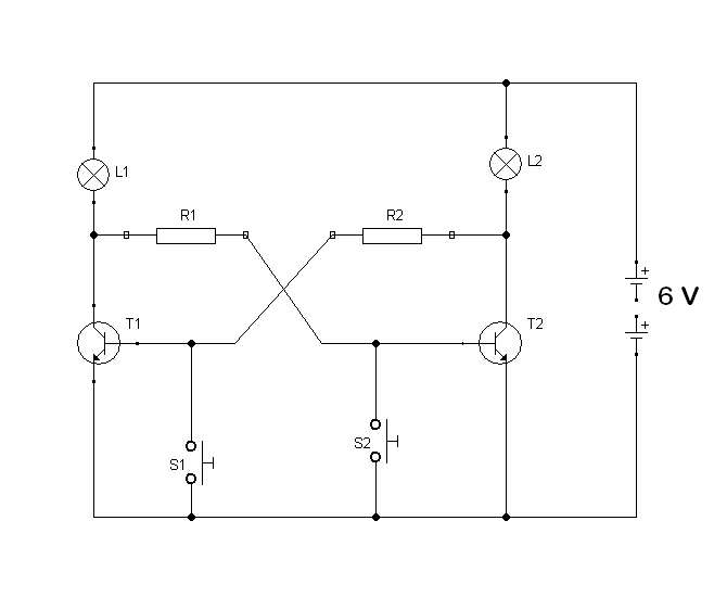
In this circuit a small current passes through L2 and R2 to the base of T1 and then through T1 to the negative wire. This is not enough to make L2 light up but is enough to turn T1 ON. A similar current passes through LI and R1 and T2. However T1 and T2 cannot both be ON at the same time because if T1 is ON then L1 is on, and the resistance of the collector-emitter circuit through T1 is low, so R1 is short-circuited and passes almost no current so T2 is OFF. So if T1 is ON T2 must be OFF (and of course visa-versa).
If we press S1 however we connect the base of T1 to the negative wire so remove the forward bias and so turn T1 OFF and then of course T2 will come ON and L2 will light up, until we press S2.
If we hold in S1 and S2 at the same time both T1 and T2 will be OFF, if we then release S1 before S2 T1 will come ON and T2 will stay OFF. If we disconnect and then reconnect the battery again one lamp and transistor will come on but we do not know which.This circuit is called a bistable because whatever state it is in it stays in that state until we deliberately change it.
Sometimes it does not matter which transistor comes on when we first connect the power but sometimes it matters very much, and we must incorporate the bistable into a circuit which ensures that it happens the way we want it.
Bistables are enormously important in very many ways: for example every single bit of a computer’s memory is a separate bistable!
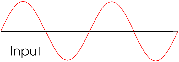
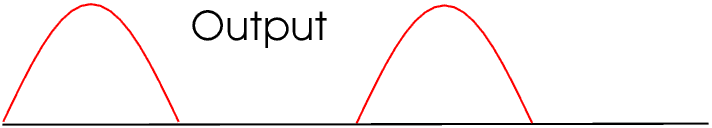
We can use a diode to convert a.c. to d.c. We can also convert a.c. to d.c. in other ways but this Section is only about diodes. If we are converting a current of more than a few milliamperes we usually call it a rectifier.
A single diode performs half wave rectification.
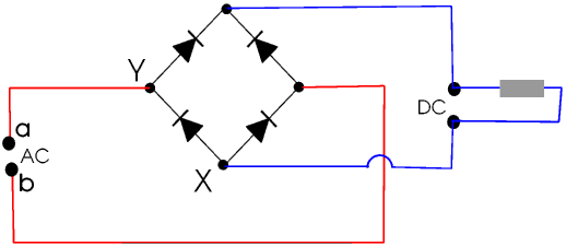
Here is full wave rectification.
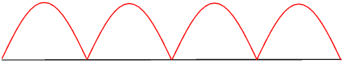
Again, for some purposes this is perfectly satisfactory but we can smooth it using a capacitor. A capacitor stores electricity as electric charges on the surface of metal plates, not like a rechargeable battery where the electrical energy is converted into chemical energy. Capacitors are described on another Page, but to understand how a capacitor can smooth a current we can consider an example using water.
We want to get a flow of water of twenty litres a minute, but we have to get the water from a well, using ten litre buckets. If we just pour a bucket of water into a pipe every thirty seconds (using a funnel of course!) we shall get out twenty litres every minute, but not in a steady stream.
Suppose however we empty the buckets into a large water tank with a pipe coming out of the bottom. The rate at which the water comes out depends on the water level in the tank: the higher the level the greater the flow. When the tank is almost empty the rate at which the water comes out is less than twenty litres a minute so the tank will begin to fill up, and at some point the water will reach a level at which the water is coming out at twenty litres a minute.
When it reaches this level every time we put in a bucket of water the water level will change a little, first rising rapidly and then falling slowly, so the flow out of the tank will be almost, but not quite completely, constant. The bigger the tank the less the change in water level and so the smoother the flow, but of course the longer it takes for the tank to fill to the right level.
We can use circuits involving semi-conductors to convert a.c to d.c., but we can also use circuits containing semi-conductors to convert d.c. to a.c. Such circuits are called oscillators. Oscillators can be used to produce sound waves, and so music and speech and other sounds.
Every electricity generator that has ever been made produces only a.c. but it is trivially simple to add a split ring commutator (this is explained elsewhere) to the generator so that it produces a full wave rectified output which can then be smoothed. We often refer to a generator used to provide a.c. as an alternator and one used to provide d.c. as a dynamo.
Photo-voltaic cells (solar panels) produce d.c. and this must be converted to a.c. before the electricity can be used about the house or supplied to the National Grid. This is also done by oscillators, although the oscillators must be able to handle much bigger currents than those in a sound system. This is discussed further on the Section on photo-voltaic cells.
A light emitting diode (LED) is a diode which emits light. It is a low-resistance component so it is almost always included in a circuit in series with a resistor.
When you are first learning about LEDs and building circuits using them it is easy to forget that the D in LED stands for diode, so unlike a lamp or resistor an LED only conducts electricity one way.
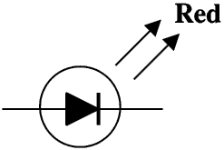
LEDs are made from naturally occurring or Man-made semiconductors. An LED producing red light can be made from gallium arsenide; different materials produce different colours.
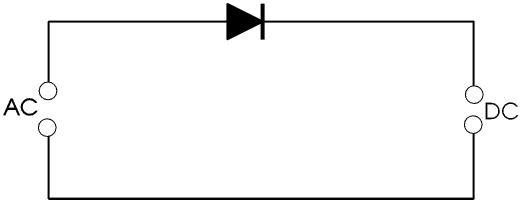
Here is the symbol for an LED. If its colour matters it is usually written onto the circuit diagram.
The first LEDs were made in the late 1950s and were red. Red is the easiest colour to make. By the early 1960s green ones were also available. LEDs were (and still are) used as status indicator lights on electronic equipment: from where I am now sitting I can see a PC, a laptop, an Acorn computer (older people might remember them from their school-days - mine is 25 years old and still going strong, I use it for maintaining this Web Site, among other things), an A3 printer-scanner, an A4 photo-real printer, a 6 × 4 (inches) dye-sublimation photo printer, a UPS, a Hi-Fi speaker system, a VHS video recorder, an Internet hub, a Revox reel-to-reel tape recorder, a colour slide scanner, a cassette tape recorder, a Network Server, a pair of HiFi cordless noise cancelling headphones, several external hard drives, a monitor screen, a multipoint USB hub and a multi-purpose memory card reader. All of them have lots of LEDs glowing at me, telling me what they are doing and how well they are doing it.
Much of the next few paragraphs is not in most school science text books, which I think is a pity.
Because of the way our eyes work we can make white light, or in fact light of any colour, by mixing red light, green light and blue light. This is more fully discussed on my Page on Colour Vision and if you have any difficulty in understanding what follows you might like to link to it. The absence of a blue LED greatly restricted the uses of LEDs because without blue you cannot make white.
Making a blue LED is incredibly difficult and involves the use of several different Man-made semiconductors. The first blue LED was not made until forty years after the first red one, and the inventors were awarded the Nobel Prize for Physics in 2014.
With red, green and blue LEDs you can make white and any other colour.
Making white light allows us to use LEDs for lighting. LEDs are by far the most energy-efficient way of providing light, converting almost half the electrical energy into light, much more than CFLs (compact fluorescent lamps, see below) or any other sort of lighting. At present 40% of all the World's electrical energy is used to provide lighting, but if we replaced everything with LEDs it would drop to 2%. You can buy LED torches and lamps for your home. An LED lamp lasts up to 20 years which is ten times longer than a CFL, it can be dimmed, uses less energy and gives a much more pleasant light, but at present LEDs are much more expensive to buy than CFLs, which is why their use is not yet widespread in this country.
Many (but not all, there are other technologies such as plasma, not described here) colour televisions and computer monitors etc use LCDs (liquid crystal displays,) to make the picture, but LCDs do not give out any light so the screen must be back-lit. We can use white LEDs to do this back-lighting. Back-lighting in this way requires lots of energy so can really only be used on mains-powered equipment or equipment powered by high-capacity (and so heavy) rechargeable batteries.
Black and white pocket calculators and digital clocks and watches use LCDs, but they do not usually use back-lighting so they can be powered by tiny disposable button cells, but they cannot be used in the dark unless they have a separate light which can be turned on only when needed. (The very earliest digital clocks and watches and pocket calculators used red LEDs but the display turned itself off after a few seconds to save power.)
Perhaps one of the most wonderful use of LED lighting is in the very poorest countries: an LED lamp powered by a battery recharged by a solar panel weighs less than a kilogram and costs a few pounds (usually donated by a sponsor or a charity or overseas aid), and in a village hundreds of kilometres from the nearest mains electricity it allows the children to go to school and do their homework and so break the cycle of deprivation and poverty.